When SONET/SDH was developed in the mid eighties its main purpose was to provide the transport technology for voice services. Two switching levels were therefore defined. Lower order switching at 1.5/2 Mbit/s to directly support the T1/E1 voice signals and a higher order switching level at 50/150 Mbit/s for traffic engineering. Switching levels at higher bit rates were not foreseen. Over time the line rate increased while the switching rate was fixed. The gap between line rate and switching bit rate got widened. Furthermore new services at higher bit rates (IP, Ethernet services) had to be supported.
The current service providers focus mainly to provide the flexibility to transport wide variety of services at higher speeds without compromising on the bandwidths. This was achieved by DWDM technology which enables high-speed switching based on wave-lengths. The DWDM technology in itself includes challenges with respect to the end-to-end traffic switching which involves multiplexing and de-multiplexing at different wave-lengths, pre-amplification, boost-amplification, line/mid-stage amplification, wave-length conversion, management, supervision and survivability of optical channels carrying client signals.
Wavelength Division Multiplexing (WDM):


• MMF is a fiber that supports multiple “lanes” of light.
• Multiple electromagnetic transmission modes are carried on MMF.
• Each lane is a different speed so that a pulse of light gets distorted sooner than in SMF.
Single-Mode Fiber
• One “lane” of light with minimum distortion
MMF SMF

Re-configurable Optical Add Drop Multiplexers (ROADM):
In fiber optics, a reconfigurable optical add-drop multiplexer (ROADM) is a form of optical add-drop multiplexer that adds the ability to remotely switch traffic from a WDM system at the wavelength layer. This is achieved through the use of a Wavelength selective switching module. This allows individual or multiple wavelengths carrying data channels to be added and/or dropped from a transport fiber without the need to convert the signals on all of the WDM channels to electronic signals and back again to optical signals.

The main advantages of the ROADM are:
-The planning of entire bandwidth assignment need not be carried out during initial deployment of a system. The configuration can be done as and when required without affecting traffic already passing the ROADM.
-ROADM allows for remote configuration and reconfiguration.
-In ROADM, as it is not clear beforehand where a signal can be potentially routed, there is a necessity of power balancing of these signals. ROADMs allow for automatic power balancing.
-The switching or reconfiguration functions of a ROADM can be achieved using a variety of switching technologies including MEMS, Liquid crystal, thermo optic and beam-steering switches in planar waveguide circuits, and tunable optical filter technology.
Measurement criteria:
The optical and digital characteristics of all the different components must be measured before using in the DWDM network scenario. The critical optical parameters to be measured in each network component are listed below.
Transponder:
- Center wavelength and spectral width of emitted channel.
- Spectral stability over time and temperature.
- Output power (max 17dBm along with laser usage regulations) and its stability.
- Sidemode suppression ratio (around 40dB)
Multiplexer and demultiplexer:
- Passband wavelengths of different channels.
- Pulse wavelength overlap (cross talk)
- Channel insertion loss
- Optical return loss (back-reflection ratio)
- Polarization mode dispersion (PMD)
- Polarization dispersion loss (PDL)
Amplifier:
- Channel center wavelength and spacing
- Spectral stability over time and temperature.
- Gain and wavelength dependence of the gain.
- Noise figure
- Output power and its stability
Dispersion compensation modules:
- Channel insertion loss
- Group velocity over wavelength.
- Chromatic Dispersion (CD)
Receiver:
- Back-reflection
- Optical and electrical bandwidth
- Sensitivity
To conclude, DWDM provides hundreds of Gbps of scalable transmission capacity today. It provides capacity beyond TDM’s capability. Supports incremental, modular growth. Transport foundation for next generation networks.
The current service providers focus mainly to provide the flexibility to transport wide variety of services at higher speeds without compromising on the bandwidths. This was achieved by DWDM technology which enables high-speed switching based on wave-lengths. The DWDM technology in itself includes challenges with respect to the end-to-end traffic switching which involves multiplexing and de-multiplexing at different wave-lengths, pre-amplification, boost-amplification, line/mid-stage amplification, wave-length conversion, management, supervision and survivability of optical channels carrying client signals.
Wavelength Division Multiplexing (WDM):
WDM combines multiple optical TDM data streams onto one fiber through the use of multiple wavelengths of light. Each individual TDM data stream is sent over an individual laser transmitting a unique wavelength of light.

WDM
Traditional, passive WDM systems are wide-spread with 2, 4, 8, 12, and 16 channel counts being the normal deployments. This technique usually has a distance limitation of under 100 km.
CWDM
Today, coarse WDM (CWDM) typically uses 20-nm spacing (3000 GHz) of up to 18 channels. The CWDM Recommendation ITU-T G.694.2 provides a grid of wavelengths for target distances up to about 50 km on single mode fibers as specified in ITU-T Recommendations. The CWDM grid is made up of 18 wavelengths defined within the range 1270 nm to 1610 nm spaced by 20 nm.
DWDM
Dense WDM common spacing may be 200, 100, 50, or 25 GHz with channel count reaching up to 128 or more channels at distances of several thousand kilometres with amplification and regeneration along such a route.
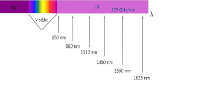
Optical Spectrum

• Light
– -Ultraviolet (UV)
– -Visible
– -Infrared (IR)
• Communication wavelengths
– - 850, 1310, 1550 nm
– - Low-loss wavelengths
• Specialty wavelengths
– 980, 1480, 1625 nm
The following figure depicts the incorporation of TDM and DWDM to offer better flexibility and serviceability by the internet providers keeping the future bandwidth requirements in view.


Basic DWDM Network and its components

A ) Transponders and Muxponders:
The main function of the transponder originally was to translate the transmit wavelength of a client-layer signal into one of the DWDM system's internal wavelengths in the 1550 nm band (DWDM wavelengths in accordance with the ITU-T grid) at the line port. Later on, the additional functionality of 3R (Re-time, Re-transmit, Re-shape) has been incorporated as further advancement.
Muxponder essentially performs some relatively simple time division multiplexing of lower rate signals into a higher rate carrier within the system (a common example is the ability to accept 4 OC-48s and then output a single OC-192 in the 1550 nm band).

B ) Multiplexer / Demultiplexer:
The Multiplexer will combine all the DWDM wavelengths received from the transponders and muxponders into one composite signal in order to transmit through the optical fibre. The Demultiplexer will perform the complete reverse process of multiplexer.

C ) Optical Amplifiers:
The An optical amplifier is a device that amplifies an optical signal directly, without the need to first convert it to an electrical signal. They can work solely in the optical domain, performing a 1R (Optical Re-Amplification). Optical amplifiers simultaneously amplify each wavelength of DWDM signal without the need of demultiplexing and remultiplexing. Usually following are the three types of optical amplifiers deployed in DWDM systems.
EDFA
SOA
RAMAN
The erbium-doped fiber amplifier (EDFA) is the most deployed fiber amplifier as its amplification window coincides with the third transmission window of silica-based optical fiber.
Types of EDFA -
- Optical Booster Amplifier
The Optical Booster Amplifier will be used at the output of the multiplexer in order to amplify the DWDM wavelengths before transmission.
- Optical Pre Amplifier
The Optical Pre Amplifier will be used before the demultiplexer in order to amplify the DWDM wavelengths after receiving from the fiber.
- Optical Line Amplifier or In-Line Amplifier
The Optical Line Amplifier will be used as the repeater at different sections of fiber where ever the amplification is required until the signal reaches the destination.
D ) Optical Supervisory Channel:
This is an additional wavelength usually outside the EDFA amplification band (at 1510 nm, 1620 nm, 1310 nm or another proprietary wavelength). The OSC carries information about the multi-wavelength optical signal as well as remote conditions at the optical terminal or EDFA site. It is also normally used for remote software upgrades and user (i.e., network operator) Network Management information. It is the multi-wavelength analogue to SONET's DCC (or supervisory channel). ITU standards suggest that the OSC should utilize an OC-3 signal structure, though some vendors have opted to use 100 megabit Ethernet or another signal format. Unlike the 1550 nm band client signal-carrying wavelengths, the OSC is always terminated at intermediate amplifier sites, where it receives local information before re-transmission.
E ) Dispersion Compensation Module:
-Dispersion:
Dispersion is a phenomenon related to the variation in velocity of different frequencies (wavelengths) or different modes. This can be either chromatic or polarization dispersion. The velocity of different frequencies can be different due to intrinsic properties of the medium or due to dispersive nature of the optical fiber.
 Polarization mode is the effect of different polarization modes (horizontal and vertical) of a signal statistically travelling at different velocities due to fiber imperfections which arise from:
-> The transport medium not cylindrical along its overall length.
-> Dopants in the fiber cladding causing high refractive index.
-> Fiber being twisted, tapered or bent at some points along the span.
-Dispersion Compensators:
A Dispersion compensator is a device that has the opposite chromatic dispersion effect as the transmission fiber. Various technologies are available that can compensate for all wavelengths in a band or for each wavelength. Compensating for all wavelengths greatly reduces the cost of compensation. Per-band compensation is used in some DWDM products. The various methods include:
- Dispersion compensation Fiber (DCF) - A type of single-mode fiber is used
- Dispersion compensation Module - A module with an element which creates a reverse behaviour of the velocity of wavelength is used.
- High order mode devices
- Virtual image phase array (VIPA) is a free space dispersion device
F ) Fiber:
Fiber is one of the most critical components of a DWDM system as it provides the physical transportation medium.The two classes of fiber used in telecommunications are multimode fiber (MMF) and single-mode fiber (SMF).
Multimode FiberThe Multiplexer will combine all the DWDM wavelengths received from the transponders and muxponders into one composite signal in order to transmit through the optical fibre. The Demultiplexer will perform the complete reverse process of multiplexer.

C ) Optical Amplifiers:
The An optical amplifier is a device that amplifies an optical signal directly, without the need to first convert it to an electrical signal. They can work solely in the optical domain, performing a 1R (Optical Re-Amplification). Optical amplifiers simultaneously amplify each wavelength of DWDM signal without the need of demultiplexing and remultiplexing. Usually following are the three types of optical amplifiers deployed in DWDM systems.
EDFA
SOA
RAMAN
The erbium-doped fiber amplifier (EDFA) is the most deployed fiber amplifier as its amplification window coincides with the third transmission window of silica-based optical fiber.
Types of EDFA -
- Optical Booster Amplifier
The Optical Booster Amplifier will be used at the output of the multiplexer in order to amplify the DWDM wavelengths before transmission.
- Optical Pre Amplifier
The Optical Pre Amplifier will be used before the demultiplexer in order to amplify the DWDM wavelengths after receiving from the fiber.
- Optical Line Amplifier or In-Line Amplifier
The Optical Line Amplifier will be used as the repeater at different sections of fiber where ever the amplification is required until the signal reaches the destination.
This is an additional wavelength usually outside the EDFA amplification band (at 1510 nm, 1620 nm, 1310 nm or another proprietary wavelength). The OSC carries information about the multi-wavelength optical signal as well as remote conditions at the optical terminal or EDFA site. It is also normally used for remote software upgrades and user (i.e., network operator) Network Management information. It is the multi-wavelength analogue to SONET's DCC (or supervisory channel). ITU standards suggest that the OSC should utilize an OC-3 signal structure, though some vendors have opted to use 100 megabit Ethernet or another signal format. Unlike the 1550 nm band client signal-carrying wavelengths, the OSC is always terminated at intermediate amplifier sites, where it receives local information before re-transmission.
E ) Dispersion Compensation Module:
-Dispersion:
Dispersion is a phenomenon related to the variation in velocity of different frequencies (wavelengths) or different modes. This can be either chromatic or polarization dispersion. The velocity of different frequencies can be different due to intrinsic properties of the medium or due to dispersive nature of the optical fiber.

-> The transport medium not cylindrical along its overall length.
-> Dopants in the fiber cladding causing high refractive index.
-> Fiber being twisted, tapered or bent at some points along the span.
-Dispersion Compensators:
A Dispersion compensator is a device that has the opposite chromatic dispersion effect as the transmission fiber. Various technologies are available that can compensate for all wavelengths in a band or for each wavelength. Compensating for all wavelengths greatly reduces the cost of compensation. Per-band compensation is used in some DWDM products. The various methods include:
- Dispersion compensation Fiber (DCF) - A type of single-mode fiber is used
- Dispersion compensation Module - A module with an element which creates a reverse behaviour of the velocity of wavelength is used.
- High order mode devices
- Virtual image phase array (VIPA) is a free space dispersion device
F ) Fiber:
Fiber is one of the most critical components of a DWDM system as it provides the physical transportation medium.The two classes of fiber used in telecommunications are multimode fiber (MMF) and single-mode fiber (SMF).
• MMF is a fiber that supports multiple “lanes” of light.
• Multiple electromagnetic transmission modes are carried on MMF.
• Each lane is a different speed so that a pulse of light gets distorted sooner than in SMF.
Single-Mode Fiber
• One “lane” of light with minimum distortion
MMF SMF

Usually Singlemode fibers are used for the DWDM transmission because of narrow core and also less attenuation.
G ) OADMs and ROADMs:
The OADM based on DWDM technology is moving the telecommunications industry significantly closer to the development of optical networks. The OADM can be placed between two end terminals along any route and be substituted for an optical amplifier. Commercially available OADMs allow carriers to drop and/or add up to four STM–16/OC–48 channels between DWDM terminals. The OADM has “express channels” that allow certain wavelengths to pass through the node uninterrupted, as well as broadcast capabilities that enable information on up to four channels to be dropped and simultaneously continue as “express channels.” By deploying an OADM instead of an optical amplifier, service providers can gain flexibility to distribute revenue–generating traffic and reduce costs associated with deploying end terminals at low traffic areas along a route. The OADM is especially well-suited for meshed or branched network configurations, as well as for ring architectures used to enhance survivability. Such flexibility is less achievable with current STM64/OC–192 offerings.
Typical Optical wavelength Add/Drop scenario:

Re-configurable Optical Add Drop Multiplexers (ROADM):
In fiber optics, a reconfigurable optical add-drop multiplexer (ROADM) is a form of optical add-drop multiplexer that adds the ability to remotely switch traffic from a WDM system at the wavelength layer. This is achieved through the use of a Wavelength selective switching module. This allows individual or multiple wavelengths carrying data channels to be added and/or dropped from a transport fiber without the need to convert the signals on all of the WDM channels to electronic signals and back again to optical signals.

The main advantages of the ROADM are:
-The planning of entire bandwidth assignment need not be carried out during initial deployment of a system. The configuration can be done as and when required without affecting traffic already passing the ROADM.
-ROADM allows for remote configuration and reconfiguration.
-In ROADM, as it is not clear beforehand where a signal can be potentially routed, there is a necessity of power balancing of these signals. ROADMs allow for automatic power balancing.
-The switching or reconfiguration functions of a ROADM can be achieved using a variety of switching technologies including MEMS, Liquid crystal, thermo optic and beam-steering switches in planar waveguide circuits, and tunable optical filter technology.
Measurement criteria:
The optical and digital characteristics of all the different components must be measured before using in the DWDM network scenario. The critical optical parameters to be measured in each network component are listed below.
Transponder:
- Center wavelength and spectral width of emitted channel.
- Spectral stability over time and temperature.
- Output power (max 17dBm along with laser usage regulations) and its stability.
- Sidemode suppression ratio (around 40dB)
Multiplexer and demultiplexer:
- Passband wavelengths of different channels.
- Pulse wavelength overlap (cross talk)
- Channel insertion loss
- Optical return loss (back-reflection ratio)
- Polarization mode dispersion (PMD)
- Polarization dispersion loss (PDL)
Amplifier:
- Channel center wavelength and spacing
- Spectral stability over time and temperature.
- Gain and wavelength dependence of the gain.
- Noise figure
- Output power and its stability
Dispersion compensation modules:
- Channel insertion loss
- Group velocity over wavelength.
- Chromatic Dispersion (CD)
Receiver:
- Back-reflection
- Optical and electrical bandwidth
- Sensitivity
To conclude, DWDM provides hundreds of Gbps of scalable transmission capacity today. It provides capacity beyond TDM’s capability. Supports incremental, modular growth. Transport foundation for next generation networks.